Distorting Object Shapes in Screen Space
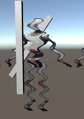
Today I’m going to walk through a different take on the distortion effect that I presented awhile ago in the post “Screen Space Distortion and a Sci-fi Shield Effect.” This time, instead of using distortion to see “through” an object, we are going to distort the shape of objects themselves. When it’s all done, it’s going to look something like this:
Pretty snazzy right? The tricky part of the effect isn’t the distortion, it’s in getting the edges of the distorted objects to sort “correctly”. Or…as correctly as the edge of an object distorted in screen space can.
All of this was done using Unity 5.5.x, so if you’ve arrived here from the future and are using a different version, you may have to tweak what I present here.
A High Level View of the Effect
Before we dive into the implementation details, here’s a quick outline of what we’re going to do to make this effect work:
- Render all the non distorting objects into our main RenderTexture
- Blit the RGB channels of that buffer into a lower res RT
- Render the distorting objects (undistorted) into the lower res RT using a custom shader
- Combine all of these buffers together to make the effect
Sounds fun right? Let’s get started.
Some Initial Set Up
The entire c# part of the effect is going to live on a single script that we’ll attach to the main camera, which we’ll get set up here.
I implemented this with two cameras, mostly so that I didn’t have to touch culling masks / settings on the main scene camera, which we use to get the color buffer that doesn’t have distorted objects in it. The script will create the second camera is the one we use to render the distorting objects.
private Camera cam;
private Camera maskCam;

public Material compositeMat;
public Material stripAlphaMat;

public float speed = 1.0f;
public float scaleFactor = 1.0f;
public float magnitude = 0.01f;

private int scaledWidth;
private int scaledHeight;
void Start ()
{

    cam                            = GetComponent<Camera>();
    scaledWidth             = (int)(Screen.width * scaleFactor);
    scaledHeight            = (int)(Screen.height * scaleFactor);

    cam.cullingMask         = ~(1 << LayerMask.NameToLayer("Distortion"));
    cam.depthTextureMode    = DepthTextureMode.Depth;

    maskCam                 = new GameObject("Distort Mask Cam").AddComponent<Camera>();
    maskCam.enabled         = false;
    maskCam.clearFlags      = CameraClearFlags.Nothing;
}
There are a few things to note here: First, we need to determine how big we want our distorted color buffer to be, so I’m mutliply the screen size by a float. This is important for optimizing the effect for low power devices. The smaller our second buffer is, the faster the effect will be, and the less memory it will use.
The other important thing to note is that I’m setting the depthTextureMode on the main camera. This is so that the camera will output a depth texture that we can see in our shaders, which we’re going to use to help us sort our distorting object later on.
The other boring bit I want to get out of the way is the update function:
void Update ()
{
   scaleFactor = Mathf.Clamp(scaleFactor, 0.01f, 1.0f);
   scaledWidth = (int)(Screen.width * scaleFactor);
   scaledHeight = (int)(Screen.height * scaleFactor);

   magnitude = Mathf.Max(0.0f, magnitude);
   Shader.SetGlobalFloat("_DistortionOffset", -Time.time * speed);
   Shader.SetGlobalFloat("_DistortionAmount", magnitude/100.0f);
}
Nothing really special here, we’re updating a bunch of values per frame so we can do things like change the scaling value at runtime, and we need to set a few shader parameters in order to update the distortion effect.
The rest of the logic for the effect is going to take place inside OnRenderImage:
private void OnRenderImage(RenderTexture src, RenderTexture dst)
{
//cool stuff goes here :)
}
If you attach this to your main camera and hit play right now, you’ll see a lovely abyss of black fill your screen. Stare into it for a moment before continuing below.

Rendering the DistortionRT
As mentioned above, the first thing we need to do in our OnRenderImage function is to get our RenderTextures filled with some colour (and depth!). Since we’re working in OnRenderImage, we already have the main camera’s output in RT form (the src argument in the function signature), but we need to get our low res colour buffer built up.
Before we render our distorting objects however, we need to copy the contents of main RT’s RGB channels into the distortingRT. This will help eliminate ugly artifacts around the edges of our wobbly GameObjects which get caused because we’re using a lower resolution image to grab their colours from. This artifact ends up looking like this:
We also need to output a specific constant into the alpha channel of the distortingRT. We are going to be using the alpha channel as a low resolution depth buffer to let us sort our distorting objects with the ones seen by the main camera, but before we do that, we need a clean slate to work with, so we need to fill the alpha channel of distortingRT with a value that represents the farthest depth possible (the far clip plane).
This is simple, but only if you’re aware of how different platforms handle depth. On some platforms (DX11/12 and Metal for example), the depth buffer goes from 1 to 0, with 1 (or white) being the closest objects, and 0 being the edge of the far plane. Other platforms (like OpenGL) go from 0 to 1. We need our shader to output the farthest depth value possible for anywhere that doesn’t contain a distorting object, so we need to output different values per platform.
Luckily, Unity has a handy preprocessor define to let us know which platform we’re using:
fixed4 frag (v2f i) : SV_Target
{
	fixed4 col = tex2D(_MainTex, i.uv);

#if UNITY_REVERSED_Z
    col.a = 0.0;
#else
    col.a = 1.0;
#endif
	return col;
}
If you aren’t familiar enough with image effect shaders to use the above snippet, the entire source for this article can be found here, but as the rest is mostly boiler plate, I’m not going to include it here.
With our shader built, we can use that to copy what we need from one buffer to the other:
private void OnRenderImage(RenderTexture src, RenderTexture dst)
{
    RenderTexture distortingRT = RenderTexture.GetTemporary(scaledWidth, scaledHeight, 24);
    Graphics.Blit(src, distortingRT, stripAlphaMat);
}
You’ll notice that instead of allocating the distortingRT earlier, we’re grabbing it here using RenderTexture.GetTemporary. The Unity docs have this to say:
If you are doing a series of post-processing “blits”, it’s best for performance to get and >release a temporary render texture for each blit, instead of getting one or two render >textures upfront and reusing them.
So that’s what we’ll do! We just have to remember to release the texture at the end of the function, otherwise we’re going to allocate a lot of RTs very quickly.
Rendering the Distorting Objects
Next we need to render the things we want to distort into the distortingRT. There’s not really much special about doing this, except that I make sure to re-set up my camera parameters every frame so that other scripts can’t accidentally mess up our rendering.
private void OnRenderImage(RenderTexture src, RenderTexture dst)
{
    RenderTexture distortingRT = RenderTexture.GetTemporary(scaledWidth, scaledHeight, 24, RenderTextureFormat.ARGBFloat);
    Graphics.Blit(src, distortingRT, stripAlphaMat);

    maskCam.CopyFrom(cam);

    maskCam.clearFlags = CameraClearFlags.Depth;
    maskCam.gameObject.transform.position = transform.position;
    maskCam.gameObject.transform.rotation = transform.rotation;
    maskCam.cullingMask = 1 << LayerMask.NameToLayer("Distortion");
    maskCam.SetTargetBuffers(distortingRT.colorBuffer, distortingRT.depthBuffer);

    maskCam.Render();
}
If you aren’t on a platform that gives you access to floating point textures, you can actually use a RenderTextureFormat.Default here, but since you’ll have so little precision in your alpha channel, distorting objects won’t sort correctly as they get farther away from the camera. For relatively small scenes (like a single room) this likely won’t be noticeable, but you’ll start to see more artifacts as your environment gets larger.
If you take a peek at your distortingRT in the inspector, you should see your distorting objects being rendered on top of a copy of what the main camera sees. In the image below, the robots are actually located behind the other geometry in world space, but they are rendered in front of it for the purposes of the distortion buffer.
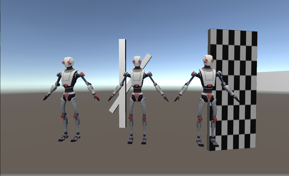
This is expected and important. If we let our distorting objects sort now, then when an object is partly occluded, we won’t have all the colour information we need to distort the object behind the occluder, leading to artifacts along the edges of occluding objects. So to address this, we’re going to let our objects render on top of everything now, and manually do the depth sorting later. It’s fun! And speaking of rendering our distorting objects, I think now is as good a time as any to talk about what needs to be in the shaders that the distorting object use.
The Distorting Object Shader
For the most part, this effect can work with any shader you want, provided you can make a small modification to the alpha output. For opaque shaders this is likely not an issue, since they don’t use the alpha channel for anything. Since transparent shaders use their alpha for blending, they’ll need a second pass to write the alpha.
As mentioned earlier, we’re going to use the alpha channel of distortingRT as a depth buffer, so that we can access them in our composite shader to do the depth sorting I was just talking about, so we need our distorting materials to output their depth into the alpha channel. Again, this isn’t a terribly complicated thing to do, but we need to be aware of platform specific differences in handling depth and clip space.
First though, we need to get the data we need from our vertex shader to the fragment. This isn’t too difficult, since all we need are the z and w components of your transformed position vector (assuming you’re transforming it by the MVP, like so):
o.pos = mul(UNITY_MATRIX_MVP, v.vertex);The Z component of this vector is what I think about when I think of depth, it represents the distance from the camera. Unfortunately this value can be well outside the 0 to 1 range that we need to be able to encode it into an alpha channel. To fix that, we can divide by the W component of the position vector, which will get us depth represented in relation to the view frustum. In DirectX, this is going to get us a value of between 0 and 1, with 1 being the far clip, and 0 being the near clip. In OpenGL, which uses a different sort of projection matrix, we’re going to end up with a value of between -1 and 1. So we need to do some quick math to make sure we don’t try to put a negative value into our texture:
float4 frag (v2f i) : SV_Target
{
//other shading logic fills RGB channels
col.a = (i.screen.z / i.screen.w);
//using UNITY_REVERSED_Z becuase SHADER_TARGET_GLSL
//doesn't seem to work on my machine
#if !defined(UNITY_REVERSED_Z)
col.a = (col.a + 1.0) * 0.5;
#endif
return col;
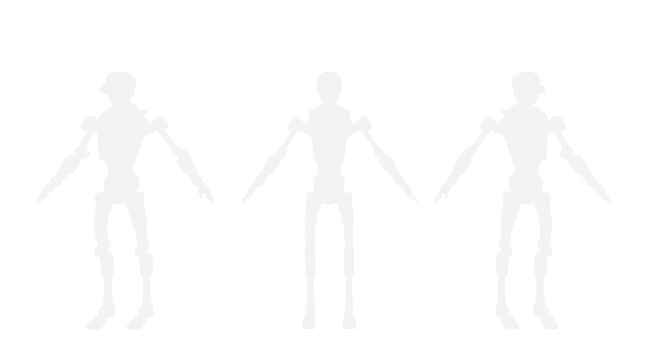
}With that modification to your shaders, if you render only the alpha channel of your distortingRT, it should look something like this:
The Composite Shader
Now all that’s left is to put this all together. The composite shader is going to be the most complicated shader we’ve talked about so far, so I’m going to provide more of the code than I have been. To start with, let’s look at the data we are going to pass the shader:
sampler2D _MainTex;
float4 _MainTex_ST;

sampler2D _DistortionRT;
sampler2D _CameraDepthTexture;

float _DistortionOffset;
float _DistortionAmount;
_MainTex is going to be the regular old colour buffer that the main camera sees, nothing special there. _DistortionRT is the buffer that we’ve been building up until now, with the RGB of our distorting objects, and their depths stored in the alpha channel.
_CameraDepthTexture is going to be the depth texture created by the main camera. This is a globally accessible resource that Unity will make for us, since we specified a depth texture mode for the main camera at the beginning of this post.
Finally, the two floating point values are to control the distortion effect. _DistortionOffset controls how fast the distortion effect moves, and as we saw earlier, is passed in as Time.time multiplied by a constant. The higher we set the constant value, the faster the distortion wiggles. _DistortionAmount is also passed in from our effect script, and controls how wide we want the distortion effect to be. Changing this value determines whether we have a subtle wobble or a spastic glitch effect.
Got it? good! I’m going to skip talking about the vertex shader because it’s just a passthrough:
v2f vert(appdata v)
{
	v2f o;
	o.vertex = mul(UNITY_MATRIX_MVP, v.vertex);
	o.uv = TRANSFORM_TEX(v.uv,_MainTex);
	return o;
}
So let’s jump directly to the good part, the fragment shader. First let’s get the values we need from the _MainTex and the _CameraDepthTexture:
fixed4 frag(v2f i) : SV_Target
{
    fixed4 screen = tex2D(_MainTex, float2(i.uv.x, i.uv.y));

    float2 distortUVs = i.uv;

#if defined(UNITY_UV_STARTS_AT_TOP) && !defined(SHADER_API_MOBILE)
	distortUVs.y = 1.0 - distortUVs.y;
#endif

    float d = tex2D(_CameraDepthTexture, distortUVs).r;
I wish I had a better explanation for the #ifdef section, but I don’t. Sometimes Unity accounts for the UV flip between platforms and sometimes it doesn’t. As far as I could tell, _MainTex is always right side up, and this set of defines will get us the correctly oriented UVs on whatever platform we’re using (I tested with GL, D3D11 and on an iPhone using Metal).
Other than that bit of engine specific weirdness, this should be pretty easy to follow so far. So let’s make it more complicated and grab our _distortionRT value.
float4 distort = tex2D(_DistortionRT, fixed2(distortUVs.x + sin((distortUVs.y + _DistortionOffset) * 100)*_DistortionAmount, distortUVs.y));This is likely confusing. All the crazy UV math is because we want to apply the distortion effect here. So we use this math to grab the colour at the position that the distortion effect needs us to read from. I went over this in much more detail in my previous post so I’m not going to talk much more about this here. For today’s purposes, here’s what you need to keep in mind:
-
Using this UV math will distort the entire _DistortingRT buffer, so if we just returned this color, the entire screen would be distorted.
-
The alpha channel still contains depth
Now that we have these values, we need to finally depth sort our distorting objects. Luckily, we now have 2 depth values, so all we need to do is compare them. In cases where the depth from _DistortingRT is closer to the camera, we want to return the RGB from _DistortingRT, and otherwise, we want to return the regular old _MainTex. Pretty easy right?
#if UNITY_REVERSED_Z
	return lerp(screen, distort, distort.a > d);
#else
	return lerp(screen, distort, distort.a < d);
#endif
Remember that different platforms handle depth differently, so depending on which platform you’re on, your comparison will need to flip, as shown above.
The entire source for the composite fragment function is as follows:
fixed4 frag(v2f i) : SV_Target
{
    fixed4 screen = tex2D(_MainTex, float2(i.uv.x, i.uv.y));

    float2 distortUVs = i.uv;

#if defined(UNITY_UV_STARTS_AT_TOP) && !defined(SHADER_API_MOBILE)
    distortUVs.y = 1.0 - distortUVs.y;
#endif

    float4 distort = tex2D(_DistortionRT, fixed2(distortUVs.x + sin((distortUVs.y + _DistortionOffset) * 100)*_DistortionAmount, distortUVs.y));
    float d = tex2D(_CameraDepthTexture, distortUVs).r;

#if UNITY_REVERSED_Z
    return lerp(screen, distort, distort.a > d);
#else
    return lerp(screen, distort, distort.a < d);
#endif
}
All we need to do now is add the final blit to the effect script, which makes the completed OnRenderImage function look like so:
private void OnRenderImage(RenderTexture src, RenderTexture dst)
{
   RenderTexture distortingRT = RenderTexture.GetTemporary(scaledWidth, scaledHeight, 24, RenderTextureFormat.ARGBFloat);
   Graphics.Blit(src, distortingRT, stripAlphaMat);

   maskCam.CopyFrom(cam);
   maskCam.gameObject.transform.position = transform.position;
   maskCam.gameObject.transform.rotation = transform.rotation;

   //draw the distorting objects into the buffer
   maskCam.clearFlags = CameraClearFlags.Depth;
   maskCam.cullingMask = 1 << LayerMask.NameToLayer("Distortion");
   maskCam.SetTargetBuffers(distortingRT.colorBuffer, distortingRT.depthBuffer);
   maskCam.Render();

   //Composite pass
   compositeMat.SetTexture("_DistortionRT", distortingRT);
   Graphics.Blit(src, dst, compositeMat);

   RenderTexture.ReleaseTemporary(distortingRT);

}
Performance Thoughts, Other Considerations
So now we should have a working effect! If you’re lost with implementing any part of this, or were just too lazy to do it yourself, all the code for the effect is available on github here.
All that’s left to do is talk about some left over details that didn’t fit anywhere else, and performance. Luckily the performance talk is short - this is a pretty lightweight effect. With a scale factor of 0.5 (so the distortion buffer is half the resolution of the main camera’s), my iPhone eats this for breakfast. This will of course become more expensive the bigger your distortion buffer is, but on such a small screen you can probably get away with a half res buffer.
And if my phone can run this… I think it goes without saying that both my laptops barely noticed this effect. I don’t have numbers because everything ran this at 60 fps and I really didn’t care to spend my weekend trying to get any more granular than that.
The other thing to mention is what could be done to make this effect better! The sine wave distortion is fairly cheesy, but you could likely extend this to handle more interesting distortion patterns if you took a few concepts from my other post on screen space distortion.
Also, since this is all in screen space, objects that are farther away from the camera appear to be distorting at a higher magnitude than objects closer to your camera. You could probably account for this by scaling the distortion magnitude based on the distorting object’s depth, but I haven’t tried this out yet.
That’s all for now, shoot me a message on Twitter if you have any questions or are doing something with this effect :)